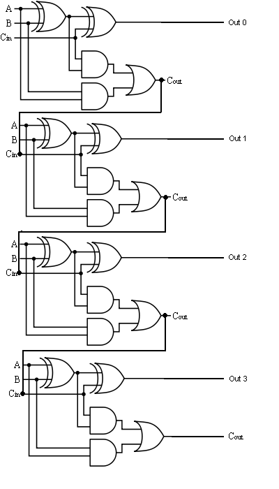
Logic gates Adder circuit logic using digital boolean implementation diagram implement function Digital logic design: full adder circuit
logic gates - How to make 2 bit or more half adder circuit - Electrical
Adder half xor logic ripple rangkaian adders transistor kombinasi Adder bit four logic gates byte 4bit nand boolean not nor values possible possibilities hold answer trick function known create Adder adders circuits libretexts pageindex
Download 4 bit adder circuit stick and logic diagram
Adder parallel addersFull adder circuit diagram Schematic diagram of a 2-bit adder: (a) 2-bit half adder is implemented6.4: 2-bit adder circuit.
The answer is 42!!: four bit full adder tutorialAdder implemented adders joining 4 bit parallel adder using full addersAdder bit circuit half make logic diagram comparator gates first electronics questions cout second only connecting solved puzzle which stack.


Digital Logic Design: Full Adder Circuit

6.4: 2-Bit Adder Circuit - Engineering LibreTexts

Full Adder Circuit Diagram

Schematic diagram of a 2-bit adder: (a) 2-bit half adder is implemented

Download 4 bit adder circuit stick and logic diagram - Educative Site

logic gates - How to make 2 bit or more half adder circuit - Electrical

The Answer is 42!!: Four Bit Full Adder Tutorial